博客
Push-pull Bottom Cap Mould
SINO MOULD specializes in the design and manufacturing of centrifuge tube moulds, including standard centrifuge tube moulds, centrifuge tube moulds with caps, and flexible combined mould solutions. Our moulds are engineered to meet medical cleanliness standards, dimensional stability, and long-term high-speed production requirements, supporting large-scale manufacturing of laboratory and medical disposable products.
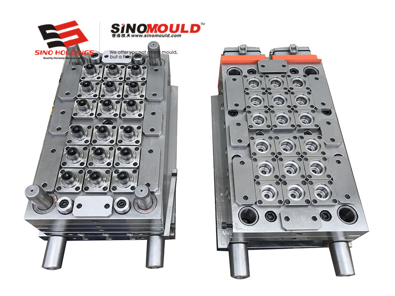
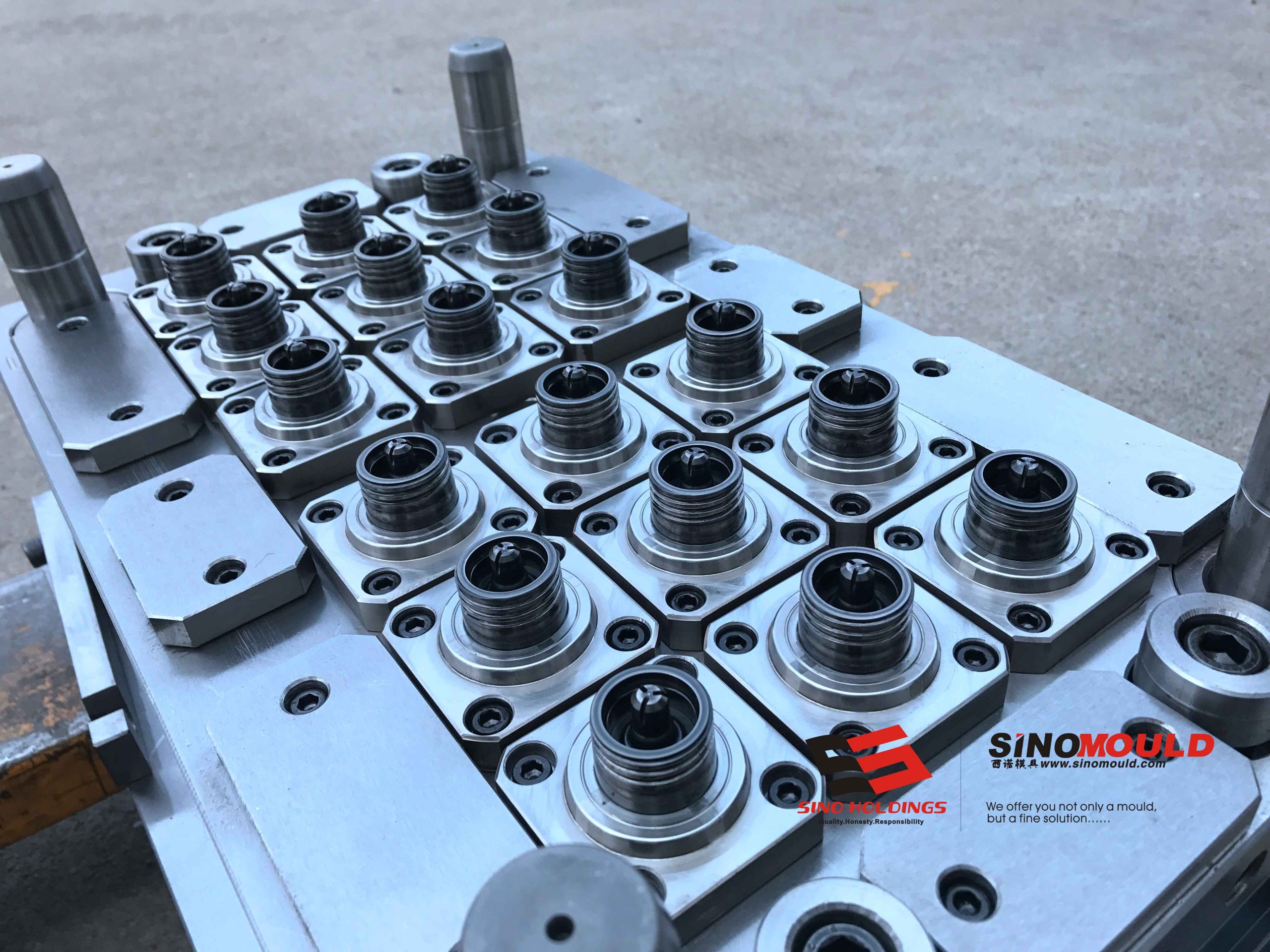
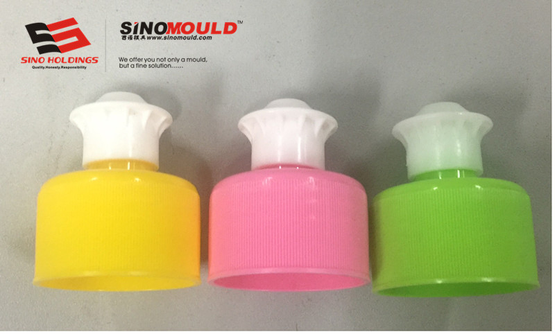
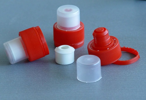
Push-Pull Bottom Cap Mould Tube Mould Details
Below are examples of the most common parameters for Push-pull Bottom Cap Mould.
| Centrifuge Tube Mould Cavity Steel | S136 / DIN 1.2316 / M340 | Recommended Injection Machine | DKM servo motor Injection Moulding Machine |
|---|---|---|---|
| Centrifuge Tube Mould Core Steel | S136 / DIN 1.2316 / M340 | Plastic Material | Medical-grade PP |
| Mould Base Standard / Steel | 4Cr13 Pre-hardened Stainless Steel | Ejection System | Stripper |
| Sliders, Inserts, Lifters Steel | High-strength tool steel with surface hardening treatment | Injection Process | High-speed injection, short cycle time, precise temperature control |
| Number of Cavities | 8–64 cavities | Injection Cycle Time | 8–12 seconds |
| Hot Runner System | Fully hot runner system | Mould Manufacturing Lead Time | 40–65 days |
Key Quality Points of Push‑Pull Bottom Cap Mould
- Precision control of sliding mechanism: Clearance between guide rail and latch is ±0.02 mm, with opening/closing life ≥5,000 cycles.
- Sealing rib corner radius R0.15–R0.2 reduces wear; insert at corresponding mold location facilitates polishing, mold adjustment, and leak prevention.
- Corrosion resistance and long service life: S136 stainless steel vacuum hardened, mold life ≥3 million cycles.
- Gate positioned away from the sealing circumference to prevent leakage caused by gate marks; large water cover can use side gate or submarine gate.
- The cavity in the sealing area must be high-gloss polished—any scratch will cause leakage.
- Cavity consistency: Naturally balanced hot runner system with independent temperature control ensures dimensional deviation ≤±0.03 mm and weight deviation ≤±0.5%.
- Interchangeable design: Standardized core and cavity inserts allow quick replacement if a single cavity is damaged.
Precision Machining Highlights for Push‑Pull Bottom Cap Mould
- High‑Precision CNC Machining: 5‑axis CNC + high‑speed engraving/milling; critical dimensions within ±0.005 mm.
- Mirror EDM Finishing: Push‑pull surfaces and sealing areas finished with mirror EDM; Ra ≤ 0.1 μm.
- Beryllium Copper Insert Cooling Optimisation: BeCu inserts are embedded in areas with wall thickness variations to ensure uniform cooling and eliminate deformation.
- Mould Flow Analysis & Trial Verification: Moldflow analysis of gate location, weld lines, and warpage; full CMM dimensional inspection after T1 trial.
Mould Flow Analysis for Push‑Pull Bottom Cap Mould
Using Mouldflow analysis, we optimize the filling, packing, and cooling processes of the centrifuge tube mould. The analysis simulates the injection moulding process, optimizing cavity layout, gate positions, and temperature control solutions, ensuring uniform cavity filling and reducing air pockets, warping, and short shots, enhancing the moulding stability of the centrifuge tube mould.