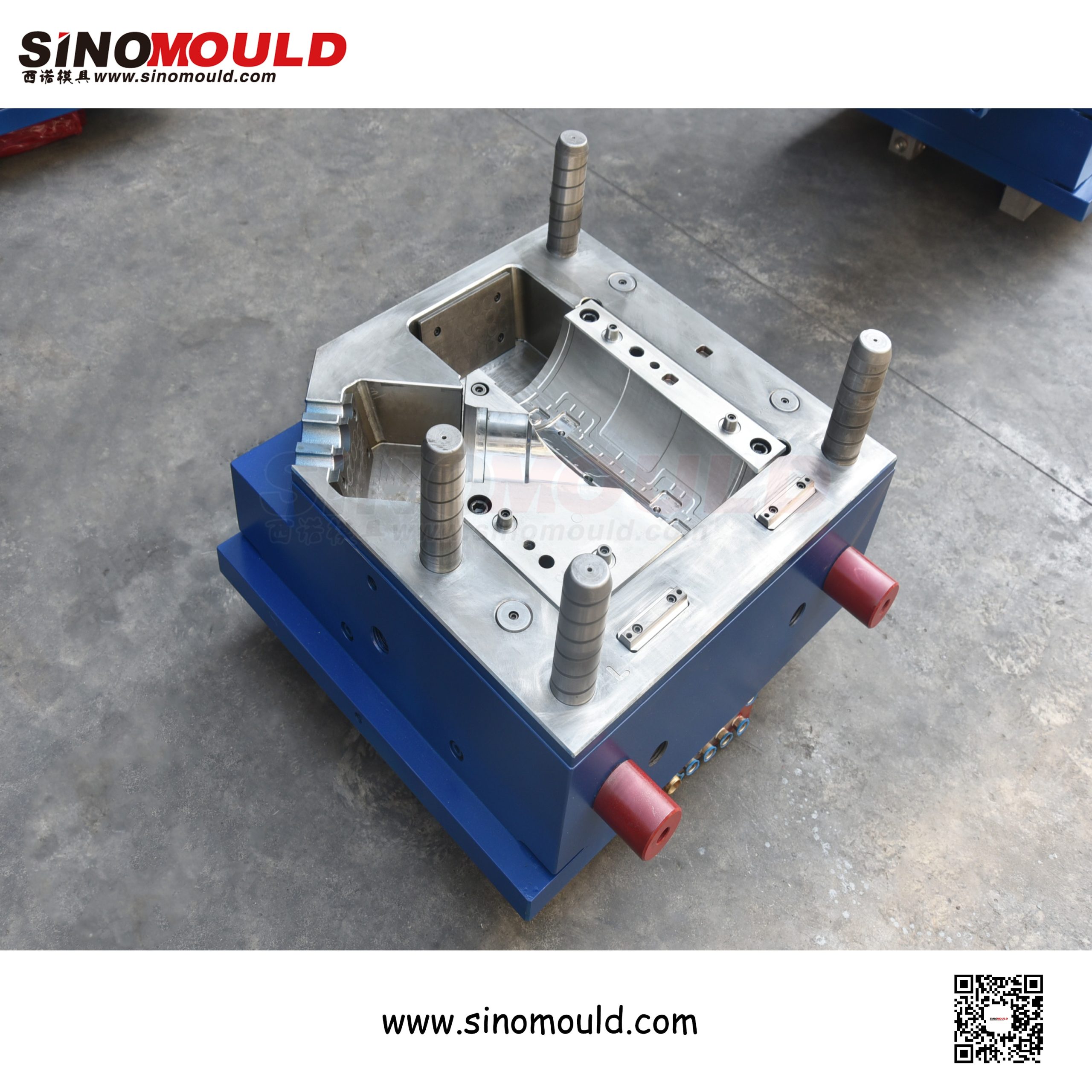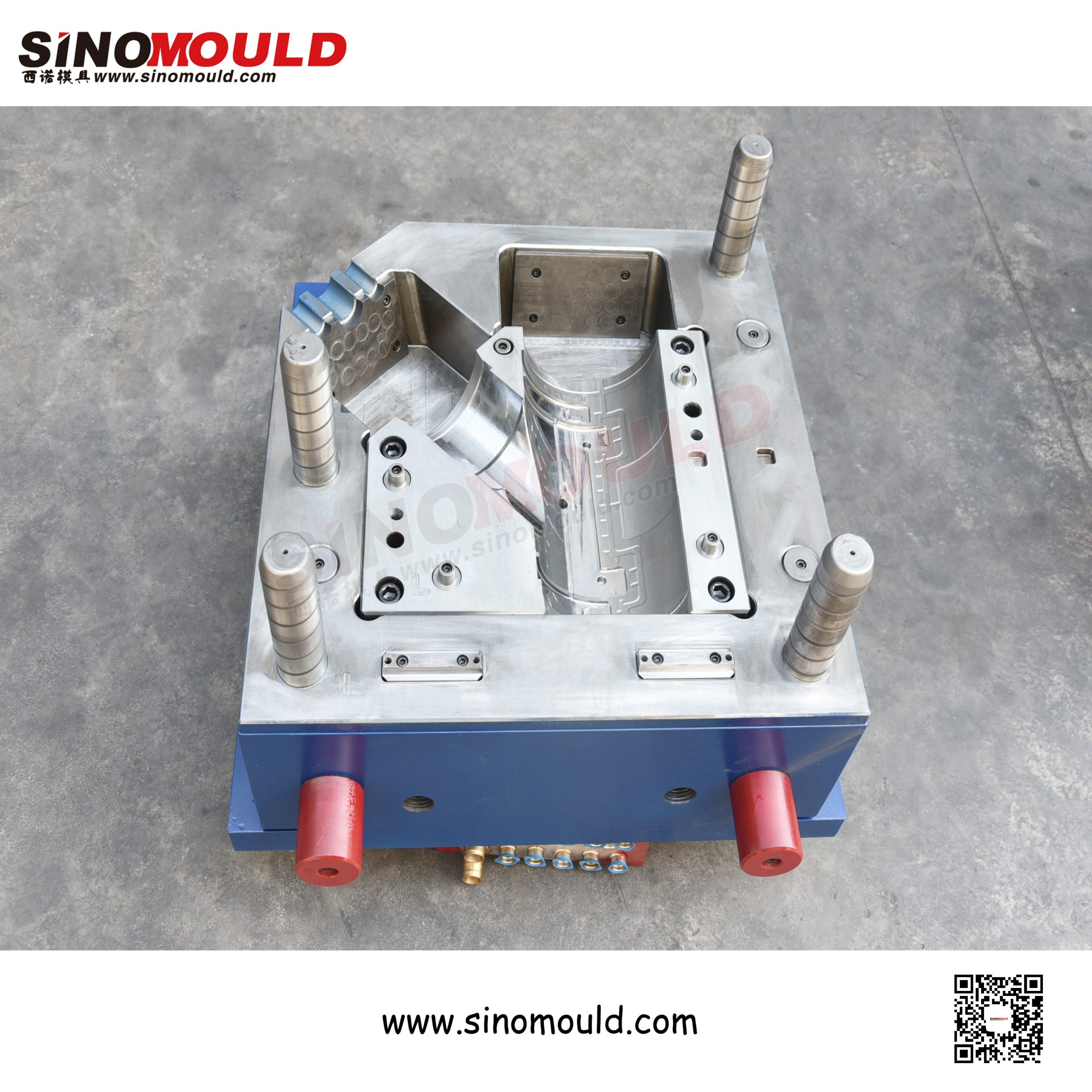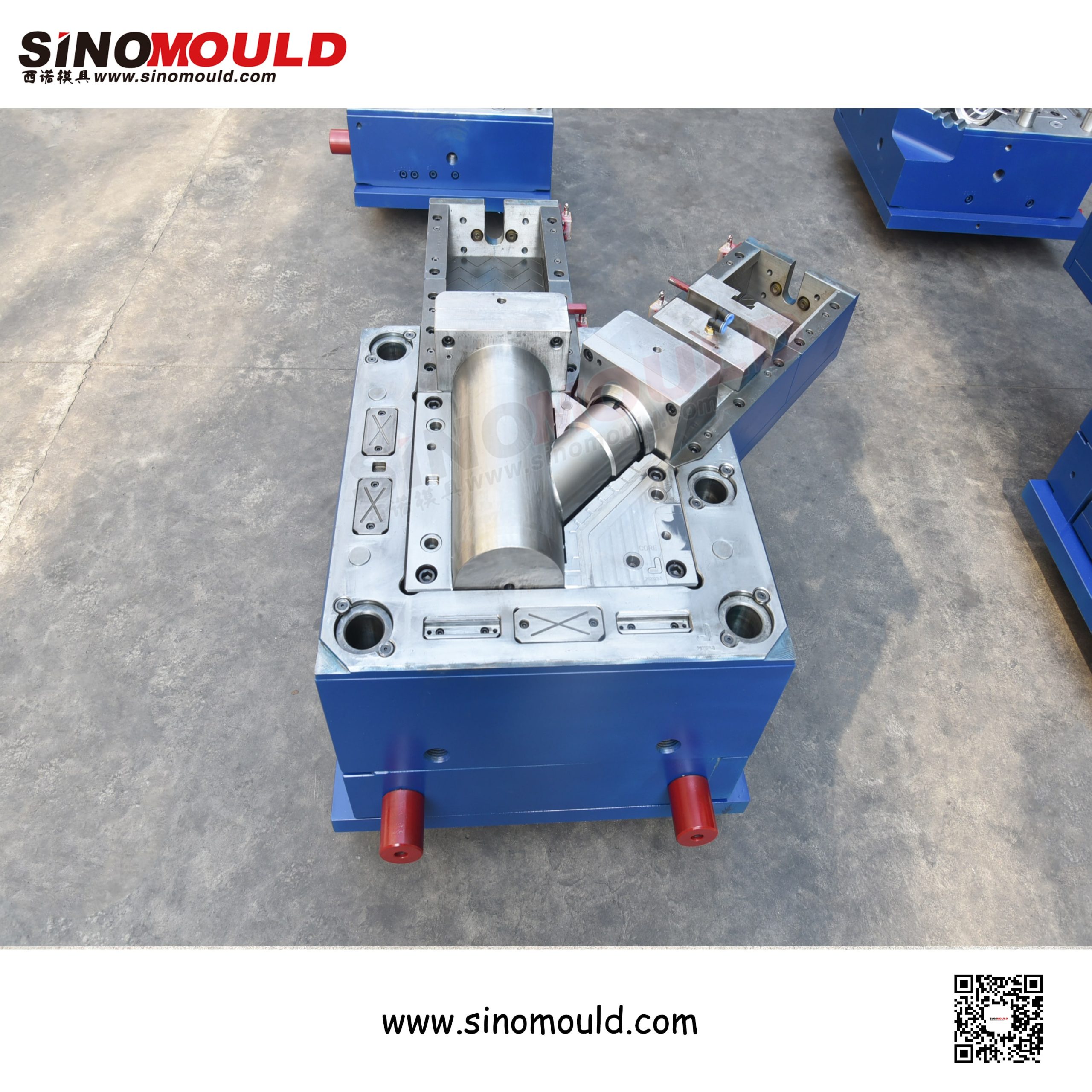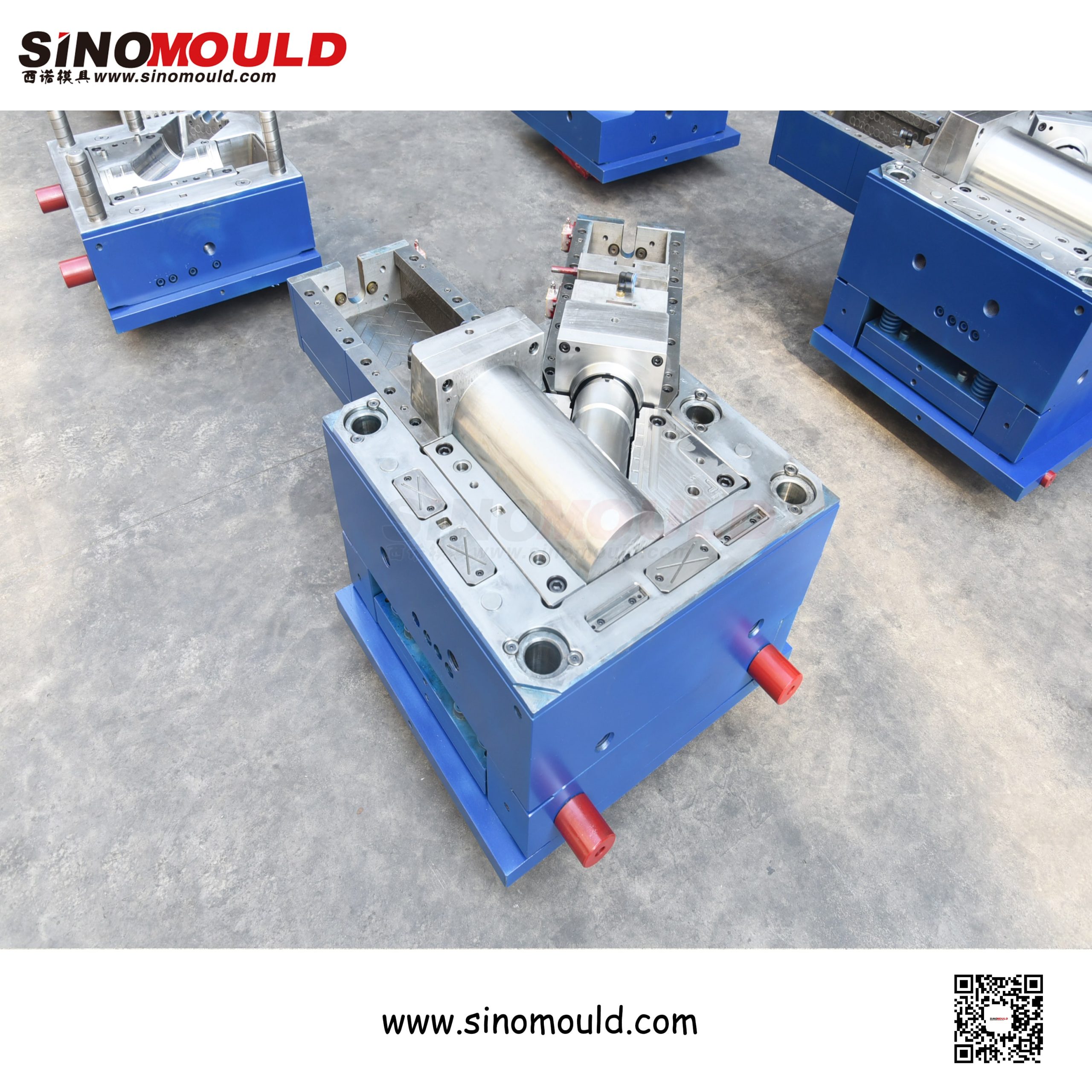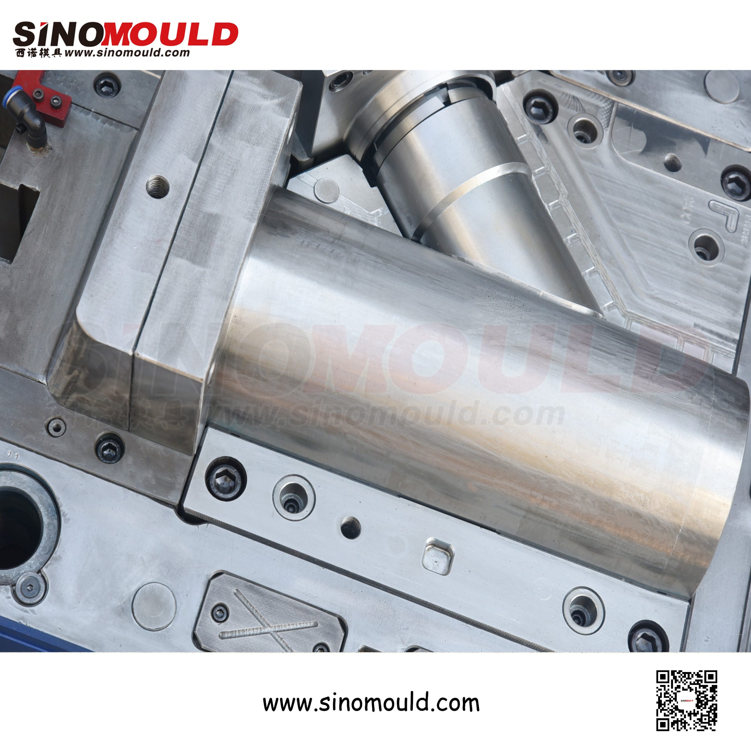
PVC 160×110 Half-Round Pipe Fitting Mould
The PVC 160×110 half-round pipe fitting is a specialised drainage component used in rainwater collection, channel drainage, and cable trench systems. Its semicircular cross-section—typically 160mm wide and 110mm high—functions as an open channel that directs water flow along walls, floors, or underground trenches. Unlike closed pipe fittings, this part requires a fully open cavity with a flat base flange, precise semicircular curvature, and smooth internal surfaces to ensure unobstructed flow and long-term resistance to sediment build-up.
This part’s large size, thin walls, and asymmetric geometry create specific moulding challenges: warpage along the long open channel, deformation at the flange edges, and the need for a robust ejection system that releases the part without cracking the curved walls. At SINOMOULD, we combine large-part machining expertise with customised cooling and ejection designs to produce half-round pipe moulds with stable dimensions and long service life. Below are the key specifications, quality priorities, and manufacturing essentials.
PVC 160×110 Half-Round Pipe Fitting Mould Parameters
| Mould Cavity Steel | DIN 1.2316, S136, 718H | Recommended Injection Machine | 350T – 800T |
|---|---|---|---|
| Mould Core Steel | DIN 1.2316, S136, P20 | Plastic Material | PVC (rigid / lead-free), PP, PE |
| Mould Base Standard / Steel | LKM Standard / S50C, S45C | Ejection System | Ejector plate + evenly distributed pins + optional air assist |
| Sliders, Inserts, Lifters Steel | High-strength tool steel, nitrided | Injection Process | Precision injection, mould temperature control ±2°C |
| Number of Cavities | 1×1, 1×2 | Injection Cycle Time | 45–90 seconds |
| Hot Runner System | Hot runner + localised cold runner (PVC-specific) | Mould Manufacturing Lead Time | 45–70 days |
PVC 160×110 Half-Round Pipe Fitting Mould Quality Control Points
- Semicircular Curvature & Cross-Section Accuracy
The core function of a half-round fitting is flow guidance, so the arc radius and cross-section height must be precise. Through matched machining of cavity and core, we hold curvature deviation within ±0.1mm and control height and width tolerances to ±0.2mm, ensuring smooth, step-free flow when multiple sections are joined.
- Warpage Control for Long Open Structures
With significant length, thin walls, and one open side, half-round fittings are prone to longitudinal bowing or opening deformation from uneven cooling. We use zoned independent water circuits along the length, combined with conformal cooling design, to equalise cooling rates across the entire channel, holding straightness within 1.5mm/m.
- Flange Edge Flatness & Sealing Surface Quality
The base flange is critical for mounting and sealing. Flange edges must be free of flash, short shots, or wavy deformation, with flatness controlled within 0.3mm to ensure tight contact with the base surface and reliable sealant bonding.
- Inner Wall Smoothness & Parting Line Control
A rough inner wall accelerates sediment build-up and reduces drainage efficiency. The parting line is positioned at the two side edges of the semicircle to avoid parting lines on the inner arc surface. The inner wall is polished to Ra ≤ 0.4μm with parting line burrs ≤ 0.05mm, ensuring smooth flow.
- PVC Thermal Stability & Environmental Compliance
PVC is temperature-sensitive and degrades at high temperatures, releasing hydrogen chloride gas. The mould uses a localised cold runner at the hot runner tip to prevent material from dwelling too long. All steels contacting the melt are corrosion-resistant grades, ensuring no rust over long production runs and compliance with lead-free environmental standards.
PVC 160×110 Half-Round Pipe Fitting Mould Manufacturing Highlights
- Precision Machining of Large Cavity & Core
Half-round fittings are large, and both cavity and core are large-scale components. We use large gantry CNC precision milling combined with wire EDM, achieving critical arc tolerances ≤ ±0.05mm and surface roughness Ra ≤ 0.4μm, ensuring a smooth inner wall and accurate curvature.
- Elongated Cooling Circuit Layout
Multiple parallel water circuits are arranged along the part’s length, each independently temperature-controlled, to prevent excessive temperature differential from long flow paths. For the heat-concentrated arc crown area, beryllium copper inserts are embedded to accelerate heat dissipation, equalising temperature along the channel and shortening the cycle.
- Balanced Gating & Filling Design
The filling path in half-round fittings is long, and a single gate can cause short shots at the far end. We use multi-point valve gate hot runners with gates evenly distributed along the length, combined with sequential control to keep the melt front advancing steadily, avoiding weld lines and short shots.
- Ejection & Demoulding Mechanism Design
Half-round fittings are thin-walled and open, prone to deformation or cracking during ejection. We use a combined ejector plate and evenly distributed ejector pins, arranged along the flange edge and arc surface, with optional air assist, ensuring balanced force and smooth, damage-free demoulding.
- Mould Rigidity & Guidance Design
Large moulds tend to deform under high injection pressure, causing flash or dimensional deviation. We thicken the mould base plates and add wear plates and locking tapers at the parting line, combined with multiple precision guide posts and bushings (clearance ≤ 0.01mm), ensuring accurate closing and stable long-term operation.
- Trial Moulding & Validation
Every mould is trial-run continuously in our in-house injection workshop under simulated production conditions. Cross-section dimensions, straightness, inner wall quality, and demoulding reliability are inspected. Only after passing these checks is the mould shipped, ensuring stable production from the customer’s first run.