Blog
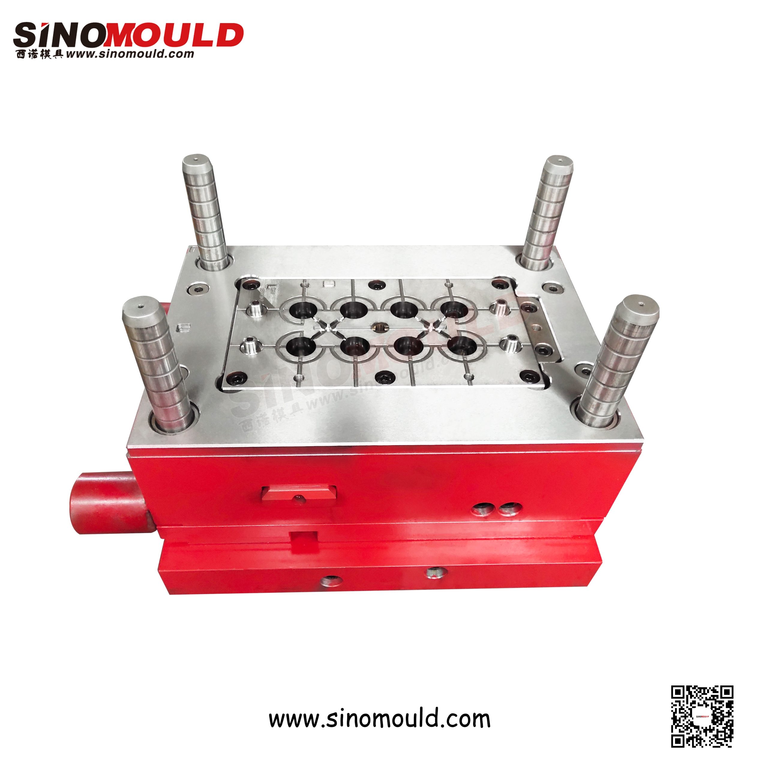
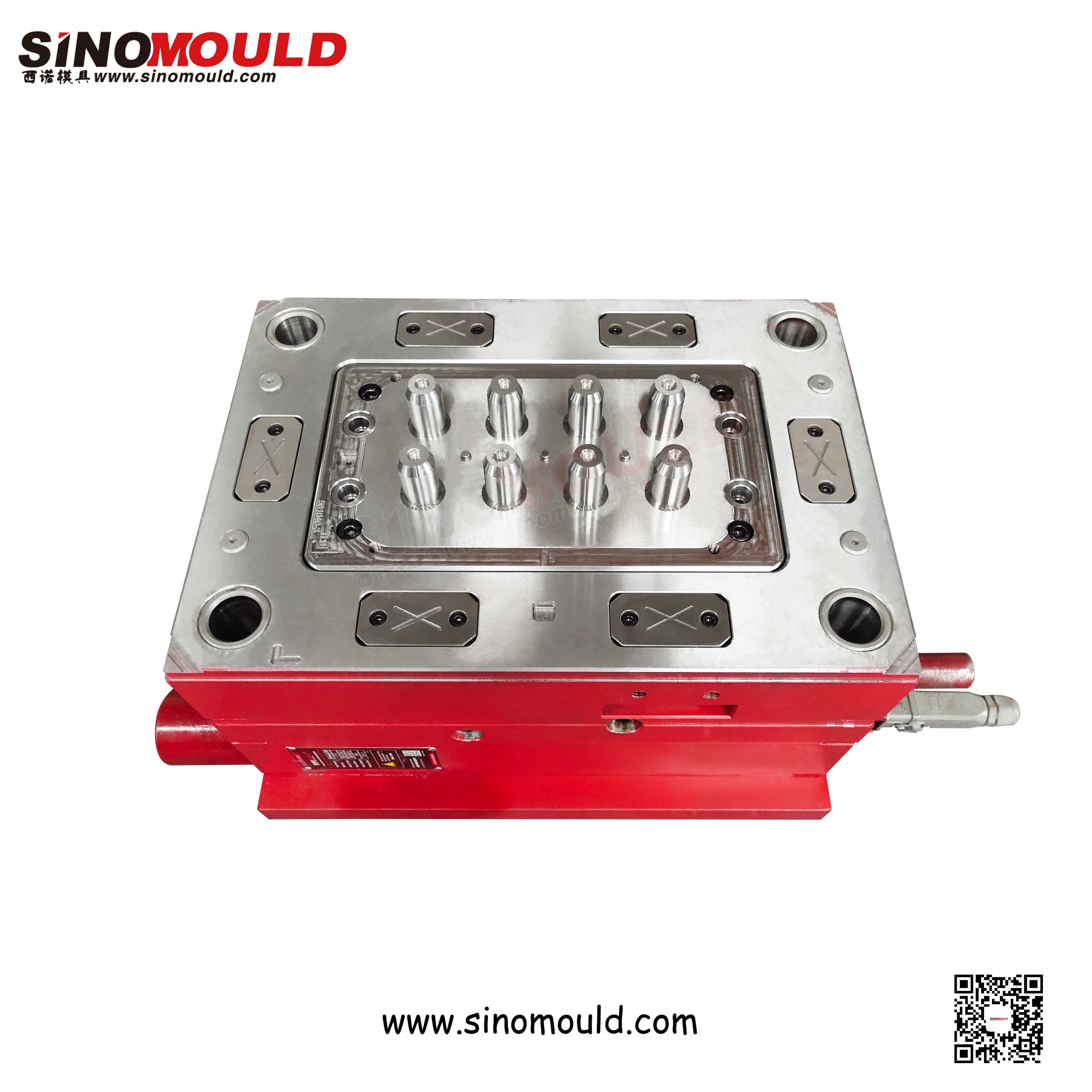
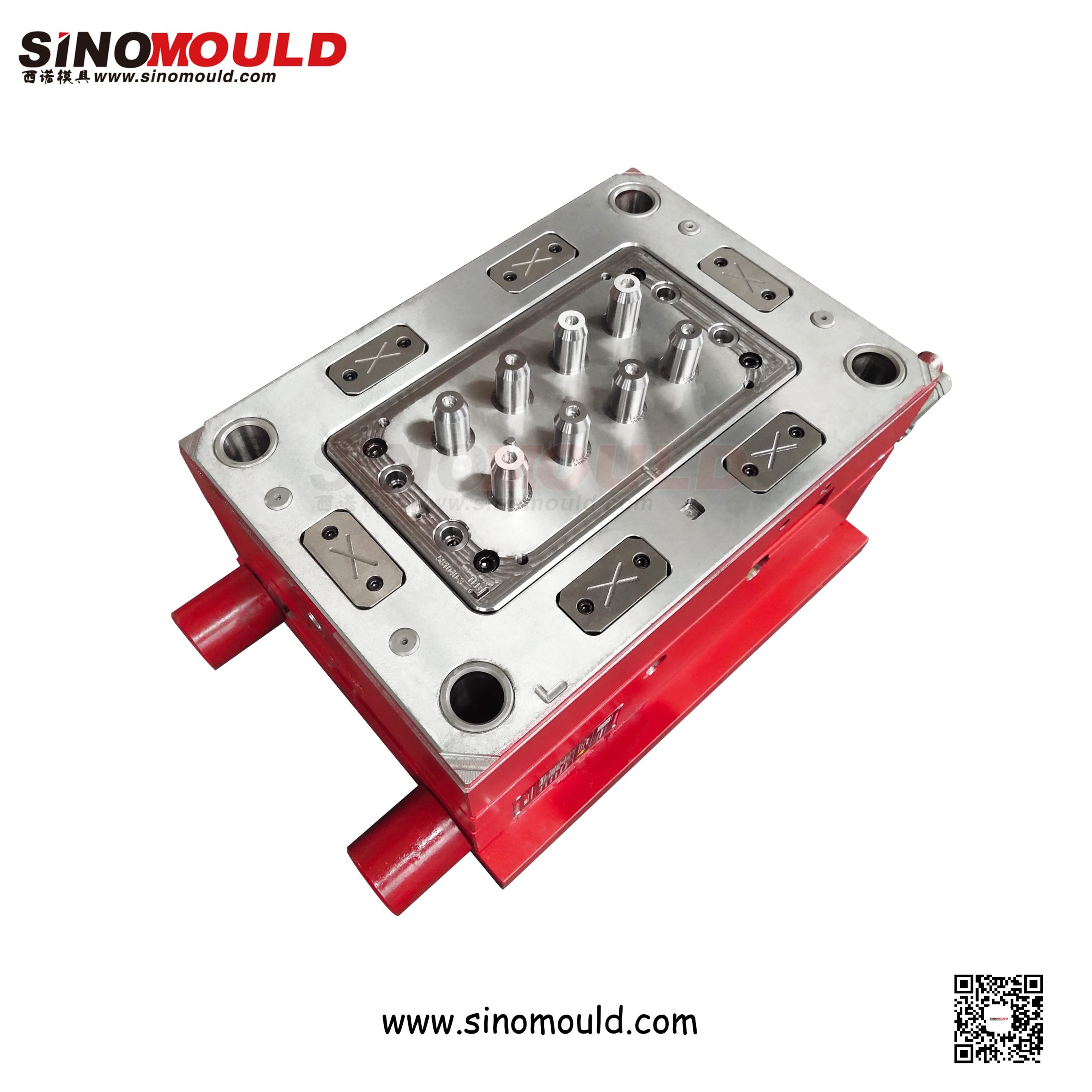
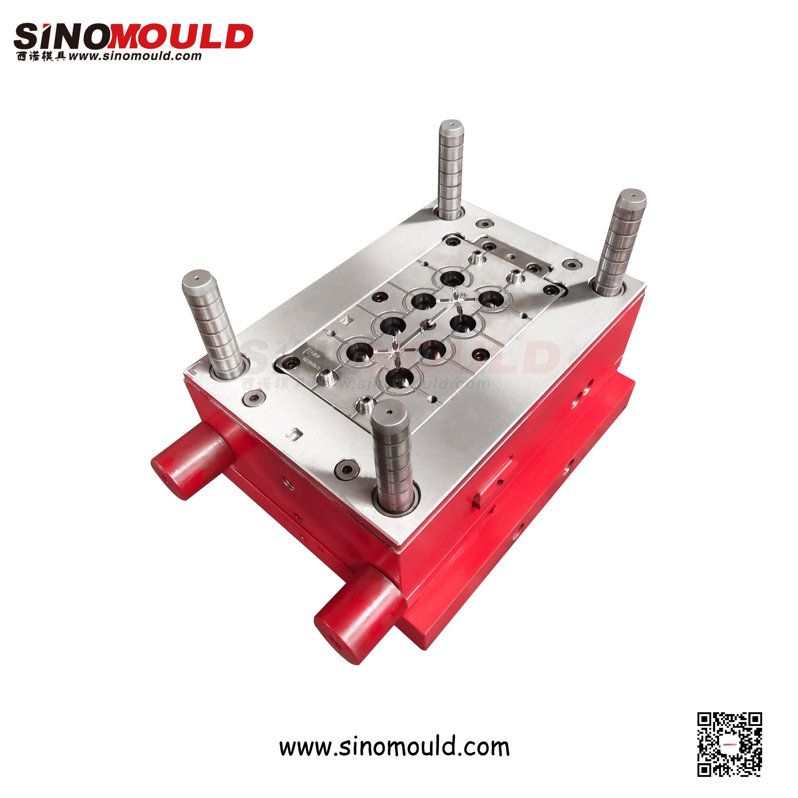
Reducing Socket Mould
The reducing socket—also called a concentric reducer or reducing coupling—connects two pipes of different nominal diameters in drainage, water-supply, and irrigation systems. Unlike a straight coupling with identical ends, the reducer must form two different socket diameters on the same axis, with a tapered transition zone between them. This geometry makes concentricity and transition-zone smoothness the dominant quality parameters: if the two socket axes are offset, the pipeline develops bending stress at the joint; if the transition is abrupt, flow turbulence and sediment accumulation follow.
Moulding this part introduces a specific challenge that same-diameter fittings do not have: the two core ends differ in diameter and must retract along a shared axis without interfering, while the transition cone must be machined to a precise angle to match the fitting standard. At SINOMOULD, we machine both core ends from a unified datum, contour the transition zone for smooth flow, and apply PVC-specific corrosion protection. The following outlines key specifications, quality priorities, and manufacturing essentials.
Standard Reducing Socket Mould Details
| Cavity Steel | DIN 1.2316, S136 | Recommended Injection Machine | 250T – 800T |
|---|---|---|---|
| Mould Core Steel | DIN 1.2316, S136, P20 | Plastic Material | PVC-U (rigid / lead-free), PP, PE |
| Mould Base Standard / Steel | LKM Standard / S50C, S45C | Ejection System | Hydraulic core pulling + ejector plate + pins |
| Sliders, Inserts, Lifters Steel | Hydraulic core pulling + ejector plate + pins | Injection Process | Precision injection, mould temperature control ±2°C |
| Number of Cavities | 1×1, 1×2, 1×4 (depending on size) | Injection Cycle Time | 25–55 seconds |
| Hot Runner System | Hot runner + localised cold runner (PVC-specific) | Mould Manufacturing Lead Time | 40–65 days |
Reducing Socket Mould Quality Control Points
- Concentricity of the Two Socket Axes
The large and small sockets of a reducer must be strictly coaxial. A concentricity deviation exceeding 0.05mm introduces bending stress during pipeline assembly and leads to joint leakage over time. We machine both core ends and cavity in a single setup from a unified datum, and use a CMM to verify the centre position of each socket bore, holding concentricity within 0.05mm.
- Transition Cone Angle & Smoothness
The transition zone is the defining feature that distinguishes a reducer from a straight coupling. The cone angle must conform to fitting standards (typically 15°–30°); excessive deviation alters local flow velocity and pressure distribution. We machine the transition cone precisely to drawing, holding angle tolerance within ±0.5° and polishing the cone to Ra ≤ 0.8μm, ensuring smooth flow from the large end to the small end with no vortex dead zones.
- Socket Inner Diameter & Taper Consistency
The large and small sockets must interchange with pipes and fittings of their respective sizes. Both core ends are machined from a unified datum, with inner diameter deviation on each end held within ±0.02mm and taper to customer standard. Each end must be verified separately; a conforming large end does not excuse a relaxed check on the small end.
- Wall Thickness Uniformity in the Transition Zone
The wall thickness in a reducer’s transition zone changes gradually from the large end to the small end. If the core and cavity do not match properly in this region, local thin spots or sink marks appear. Cavity-to-core matching clearance is controlled to ±0.03mm, and mould flow analysis optimises packing in the transition zone, ensuring uniform cone wall thickness with no visible sink marks.
- PVC Thermal Stability & Cavity Corrosion Protection
PVC degrades at elevated temperatures, releasing hydrogen chloride that corrodes cavities and affects part appearance. The mould uses a localised cold runner at the hot runner tip to prevent material dwell; cavity steels are corrosion-resistant grades such as 1.2316 or S136, ensuring no rust or material build-up over long production runs.
Reducing Socket Mould Manufacturing Highlights
- Dual-Diameter Cores from a Unified Datum
The heart of a reducer mould is the dual-diameter core. We mount the large-end and small-end cores on the same rotational datum for machining: turning the outer diameter and cone first, then using the finished outer diameter as the datum to machine the socket forming surfaces, ensuring the rotational axes of both core ends coincide exactly. After machining, concentricity is re-verified with the cores in their assembled state, avoiding the common problem of individually conforming parts that run eccentric once assembled.
- Streamlined Transition Cone Machining
The transition cone is machined by CNC turning followed by hand polishing: the cone is first precision-turned to drawing angle, then polished with an oilstone in a single direction along the cone’s generatrix to avoid transverse polishing marks that disturb flow. The junctions between the cone and both socket bores are radiused to eliminate sharp corners, ensuring fluid entering from the large end converges smoothly to the small end without vortex formation or material accumulation.
- Two-Stage Core Pulling & Sequential Control
Because the two core ends differ in diameter, demoulding must follow the correct sequence: the large-end core withdraws first, followed by the small-end core, preventing the two cores from squeezing each other in the transition zone. We use hydraulic core pulling with dual switch control, with stroke and speed set independently for each stage, ensuring accurate action and no jamming over long production runs.
- Multi-Point Gating & Transition Zone Feeding
The large end of a reducer usually has thicker walls than the small end, and a single gate cannot adequately feed both. We arrange multi-point valve gates near the large-end and small-end outer walls, with sequential control ensuring sufficient packing in the thicker large-end region and preventing sink marks on the transition cone. Gate locations avoid socket sealing surfaces so gate vestige does not affect fit accuracy.
- Mould Rigidity & Core-Pulling Guidance
The two-stage core-pulling mechanism has many moving parts; insufficient mould rigidity causes core wobble and misalignment during closing. We thicken the mould base plates, locate core-pulling slides with wear plates and locking tapers, and use multiple precision guide posts and bushings (clearance ≤ 0.01mm), ensuring the two core ends are coaxial in the closed position and do not wobble during withdrawal.
- Trial Moulding & Validation
Every mould is trial-run continuously in our in-house injection workshop under simulated production conditions. Concentricity of the two ends, socket dimensions, transition cone angle and surface quality, wall thickness uniformity, and two-stage core-pulling reliability are inspected. Only after passing these checks is the mould shipped.