Blog
Reducer Mould
An reducer mould connects a smaller pipe to a larger one. It is the tool behind the fitting that lets a DN25 branch feed a DN32 header, or a 50 mm drainage run open into 75 mm, without a separate adapter and a second joint. Buyers rarely ask for it by that name: in catalogues the same part appears as an reducer, a bell reducer, a reducing coupling or a reducer. What matters at the tooling stage is not the label but the two socket sizes, the wall schedule and the resin. This guide covers how an reducer mould is built, what to specify, and where cheap tooling starts to cost money at the press.
Reducer Mould Details
| Mold Cavity Steel | S136 / DIN 1.2316 / M340 | Parameter | Specification |
|---|---|---|---|
| reducer Mold Core Steel | S136 / H13, 48–52 HRC, nitrided core | Plastic Material | PP-R / PE100 / HDPE, pipe-grade low-MFI |
| Mold Base Standard / Steel | LKM / HASCO standard base, S50C / P20 pre-hardened | Ejection System | Stripper plate / sleeve ejection, no ejector marks on the bore |
| Sliders, Inserts, Lifters Steel | 718H slider bodies; S136 / H13 inserts nitrided 58–60 HRC | Injection Process | High-speed injection, short cycle time, precise temperature control |
| Number of Cavities | 8–64 cavities | Injection Cycle Time | 8–12 seconds |
| Hot Runner System | Fully hot runner system, open nozzle or valve gate by resin | Mold Manufacturing Lead Time | 40–65 days |
What Is an reducer Mould and What Does It Produce?
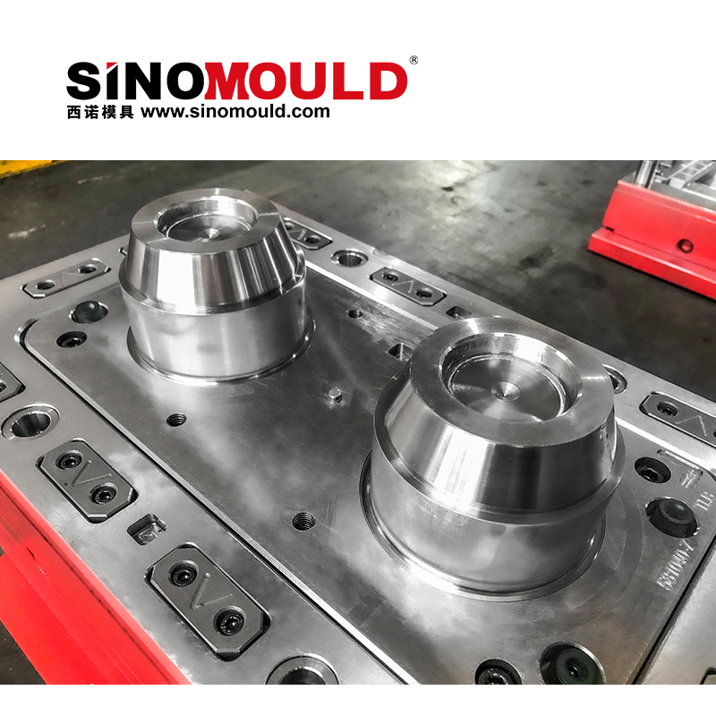
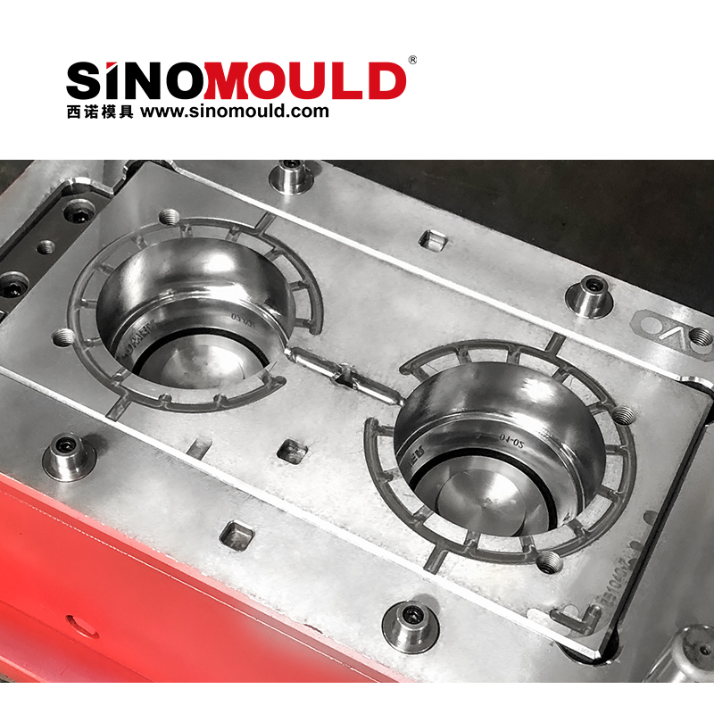
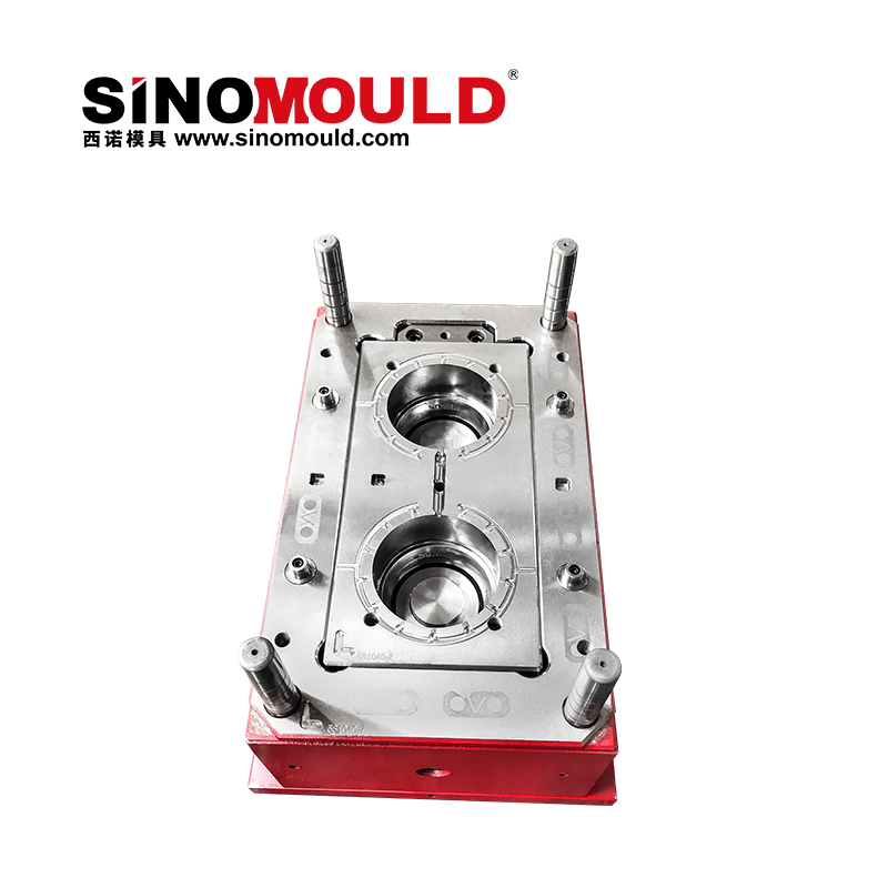
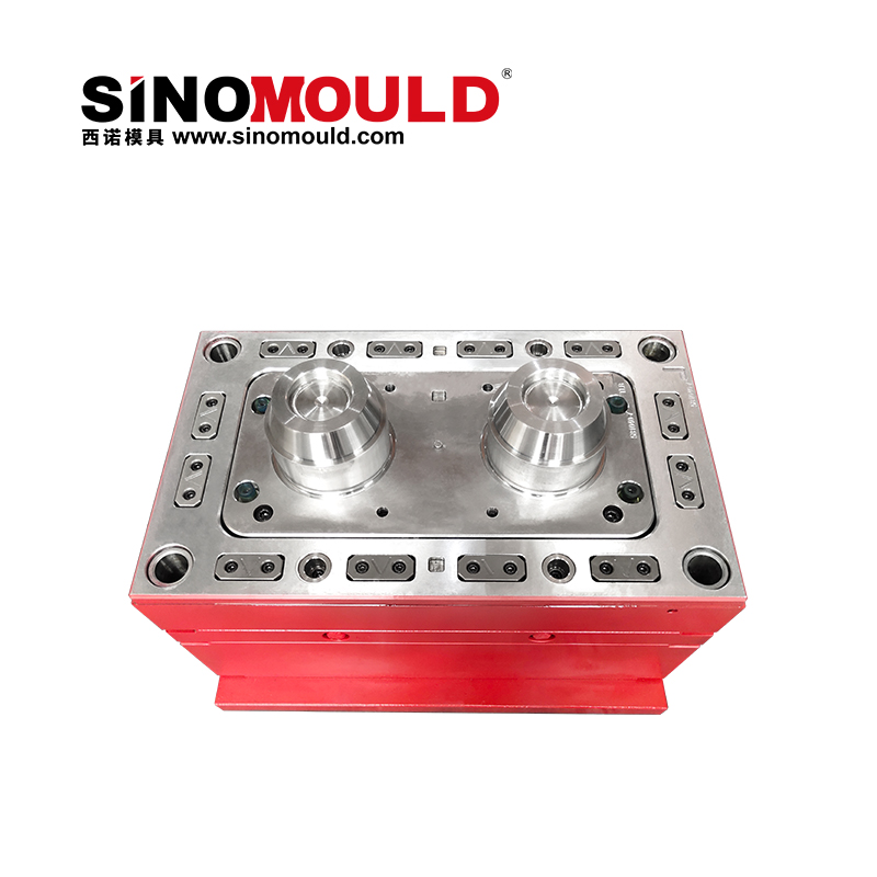
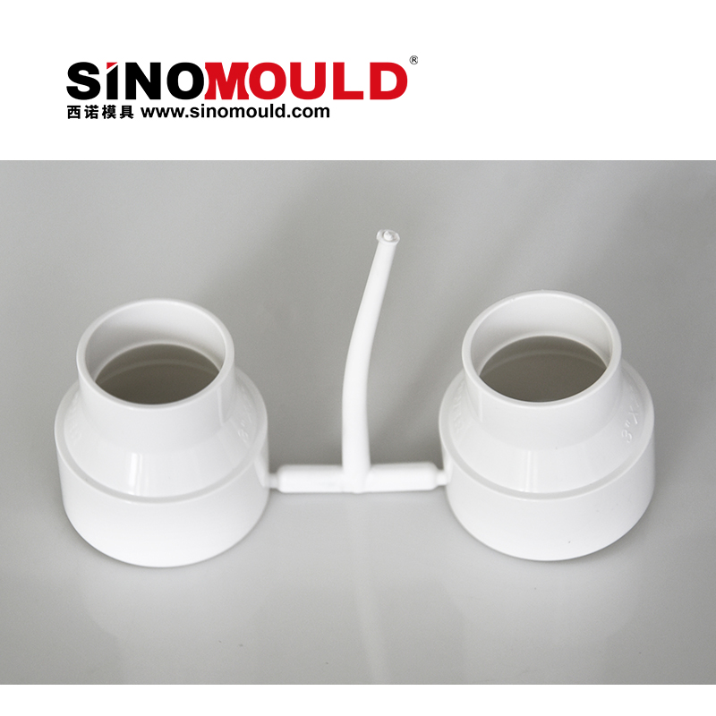
An reducer mould is an injection mould that produces a one-piece fitting with two different socket diameters, a small socket on one end and a large socket on the other, so a pipeline can step up in size at a single joint. The mould carries a cavity for the outer form, a core for the bore, and usually a separate insert or slider for the transition step where the two bores meet.
reducer moulds run in the same plants as elbow, tee and coupling tooling: PPR hot and cold water systems, PE100 and HDPE water mains and irrigation headers, PVC-U drainage and soil stacks, ABS and CPVC industrial lines, and PE gas piping. Dimensionally the fitting is governed by the product standard rather than the mould maker’s preference — ISO 15874-3 for PPR, ISO 4427-3 for PE, ISO 1452-3 for PVC-U. A usable reducer mould is cut to the socket dimensions of the standard the customer sells into, then checked against the gauge that customer’s own QC uses.
reducer Mould vs Reducer Mould: The Naming Trap
Reducer and reducer describe the same fitting seen from opposite ends. Flow from the small socket to the large socket reads as an reducer; flow the other way reads as a reducer. The cavity is identical, only the catalogue description changes. That is why RFQs arrive under both names, and why a supplier who quotes “a 32 mm reducer” without asking for the second dimension is guessing.
The practical rule is to specify the part by socket pair, not by flow. “32 × 25, socket fusion, PN20, PPR” is a complete brief. “32 reducer” is not: it could be 32 × 25, 32 × 20 or 32 × 40 depending on the market. An reducer mould built to the wrong pair is scrap steel, not a rework.
Six Decisions That Set the Yield of an reducer Mould
Transition geometry. The ring where the small bore opens into the large one is the thickest section of the part and the last to freeze. Gate it deliberately, with a hot drop into the transition or a side gate at the large end, and vent the step so the ring does not burn.
Core strategy. The small-end core is long and slender relative to its diameter, so it deflects under injection pressure and drags on the part during ejection. A tapered core with air pop suits short sockets; a collapsible core suits deep sockets and threaded ends; a loose insert suits low volume at large sizes.
Shrinkage per resin. Cut the cavity for the resin, not for a nominal size: PVC-U 0.5–1.5%, PPR 1.5–2.0%, PE100 2.0–3.0%. An reducer mould cut for PVC-U and re-set for PP will not hold the socket, and the correction is a new cavity insert rather than a tuning pass.
Bore finish. The small socket is usually the sealing end. Polish along the draw direction, keep ejector marks out of the sealing zone, and agree the finish (SPI B1, B2 or mirror) in writing before steel is cut.
Cavitation and balance. 8–16 cavities for DN20–25, 4–8 for DN32–90, and 1–2 with a hot runner above DN110. Balance the runner on the large-end side, because a starved small end shows up as a short shot at the transition ring.
Core cooling. A baffle or bubbler in the small-end core cuts cycle time more than cavity cooling does, because the core is the heat trap. Expect 25–60 s cycles depending on wall thickness and how well that core is cooled.
Have an reducer mould in the RFQ stage? Send the fitting drawing with resin grade, annual volume and press tonnage. SINO returns a cavity layout, steel proposal and cycle estimate within two working days. Request an reducer mould quote →
How SINO Qualifies an reducer Mould Before It Ships
An reducer mould is only proven on the press, so the release package is built around the trial, not the drawing. Every tool leaves the plant with:
- Steel certificates for cavity and core, with hardness checked at three points on the core
- CMM report on socket IDs, transition position and end squareness
- Cooling circuits pressure-tested at 6 bar for 30 minutes, with a flow check per circuit
- A T1 trial run on the customer’s resin and masterbatch, not a house substitute
- A four-hour capability run at fixed parameters, recording cycle, shot weight, socket ID at start and end, and scrap rate
- Rust prevention, a spare core and wear-parts list, a trial video and a mould map
What Drives the Cost and Lead Time of an reducer Mould
Two tools of the same size can differ by a factor of three in price, and the gap is almost always in the core and the cavitation. Sixteen cavities triple the steel and machining but drop piece cost. A collapsible core adds design and machining hours, while a loose insert is cheaper to build and slower to run. Mirror polishing in the bore is hand work. A hot runner raises tool cost and cuts scrap on thick transitions. Trial documentation is cheaper when the customer supplies resin, colour and gauge early.
Lead time follows the core. A fixed tapered core with air ejection ships inside the 30–45 day band; a collapsible core with segmented slides usually adds two weeks.
How to Choose an reducer Mould Supplier
Four questions separate a tooling partner from a trading desk:
- Do you cut per-resin shrinkage, or use one cavity for PVC and PP? The answer should be per-resin, with a documented shrink table.
- Can you build and service a collapsible core in-house, and what do a spare core and its lead time cost?
- Will T1 run on our resin, and exactly what is in the trial report?
- Who corrects a socket that drifts out of tolerance after 200,000 shots, and at whose cost?
reducer Mould FAQ
Is an reducer mould the same as a reducer mould? In geometry, yes; in documentation, no. Both produce a fitting with two different socket sizes, and the name only follows the flow direction. Always quote the socket pair and the standard.
Can one reducer mould run PVC-U and PPR? No. Shrinkage, melt behaviour and wall design differ enough that the cavity must be cut per resin. The frame, ejection and cooling layout can often be shared across a fitting family.
How many cavities should an reducer mould have? Below DN25, 8–16 cavities pay back within a year at volumes above roughly 200,000 pieces. DN32–90 usually runs 4–8 cavities; DN110 and above runs 1–2 with a hot runner.
What do you need to quote an reducer mould? A 2D drawing or STEP file with socket IDs and wall schedule, the resin and grade, the target standard, annual volume, press tonnage, and the gauge or customer who will approve the part.
Building a range, not a single size? Most fitting plants start with one reducer mould and add the family later. Ask SINO for a family tooling plan that shares frames, ejection and cooling across 25×20, 32×25, 40×32 and 50×40, and keeps the spare-parts list short.