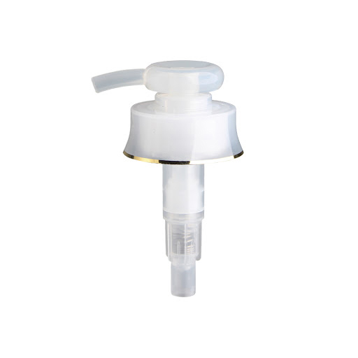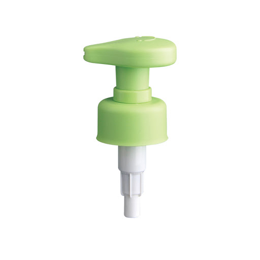
Pump Cap Mould
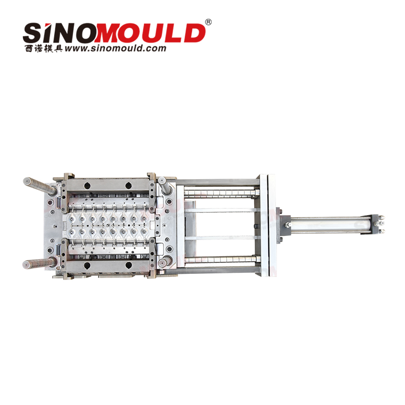
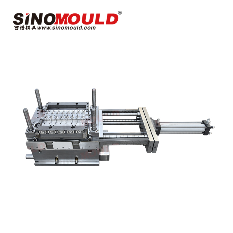
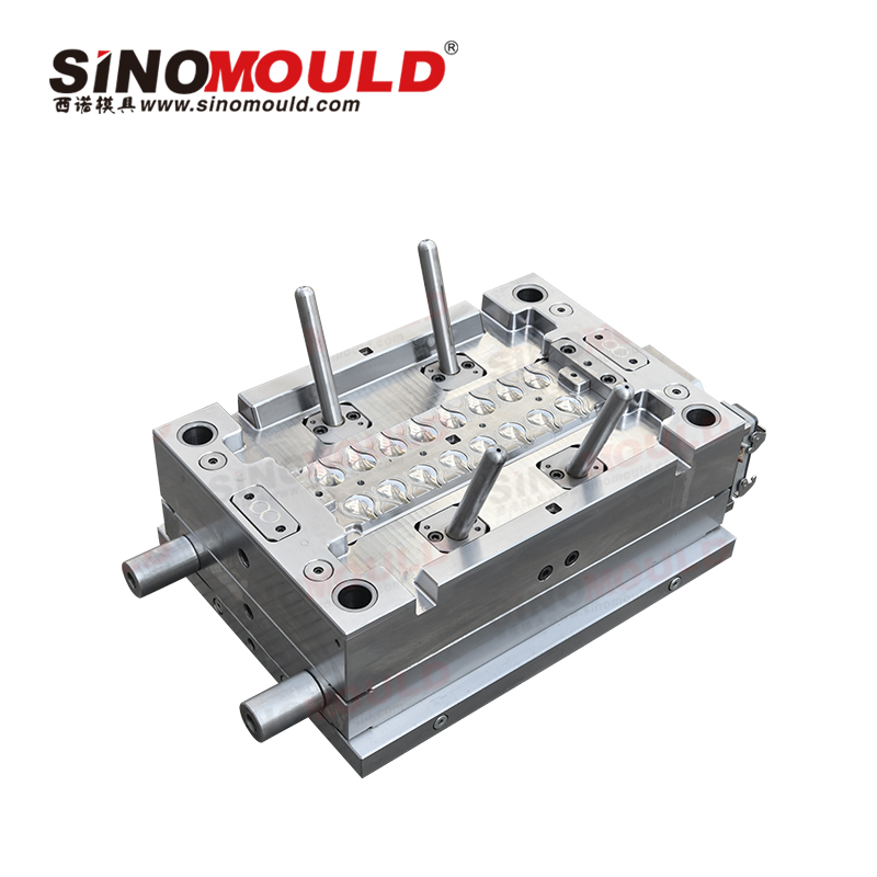
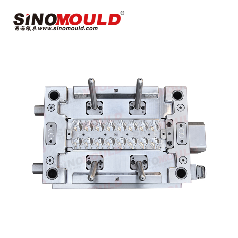
SINOMOULD’s pump cap mould is designed to meet the specific requirements of thin walls, high aesthetic standards, and precise snap‑fit engagement. Using mirror‑grade corrosion‑resistant steel, a valve‑gated hot runner system, conformal cooling, and balanced ejection design, this mould ensures a flawless appearance free from sink marks and weld lines, stable dimensional fit, and a short injection cycle – suitable for high‑volume production of PP and other materials.
Pump Cap Mould Specifications
Below are examples of the most common parameters for Centrifuge Tube moulds.
| Pump Cap Mould Cavity Steel | S136H | Recommended Injection Machine | 200T–250T servo injection molding machine |
|---|---|---|---|
| Pump Cap Mould Core Steel | S136H / 1.2344 ESR (HRC 48–52) | Plastic Material | PP (MFI 20–35 g/10min) |
| Mould Base Standard / Steel | LKM standard, S50C/P20 | Ejection System | Stripper plate + ejector pins + angled lifters + pneumatic assist |
| Sliders, Inserts, Lifters Steel | Slides/lifters: 1.2344 ESR hardened HRC 48–52; Inserts: S136H | Injection Molding Process | Mould temperature 30–60°C, melt temperature 200–230°C, injection pressure 80–120 MPa, holding pressure 50–70 MPa |
| Number of Cavities | 8–64 cavities | Injection Cycle Time | 18–22 seconds |
| Hot Runner System | Valve‑gated hot runner system (YUDO/HRS/Mold‑Master) | Mould Manufacturing Lead Time | 35-40 days |
Pump Cap Mould Quality Control Points
- Appearance Quality
Cavity polished to SPI A1/A2 with surface roughness Ra ≤ 0.025 μm. Product surface must be free from sink marks, weld lines, flow marks, flash, ejector marks, and gate marks.
- Dimensional Fit Accuracy
Critical internal hole and snap‑fit position tolerances controlled within ±0.05 mm, coaxiality ≤ 0.05 mm – ensuring stable, secure fit between the cap and pump body.
- Multi‑Cavity Consistency
Valve‑gated hot runner and balanced gate design ensure consistent filling across cavities, with part weight variation between cavities ≤1.5% and stable colour and shrinkage.
- Cooling and Deformation Control
Conformal cooling + baffe‑type water circuits maintain mould temperature uniformity within ±3°C, effectively controlling flatness and roundness deformation of the thin‑wall cap.
- Demoulding Reliability
Balanced ejection via ejector pins, stripper plate, and angled lifters, with a pre‑return mechanism to prevent ejector marks, drag marks, and snap‑fit fracture.
- Mould Life
Cavity and core made from corrosion‑resistant mirror steel; slides and lifters hardened to HRC 48–52. Under normal mass production conditions, mould life exceeds 500,000 cycles.
Pump Cap Mould Machining Essentials
- High‑Speed Milling
Roughing allowance: 0.15–0.20 mm. Finishing uses small‑diameter cutters for corner cleaning to ensure sharp contours and distinct edges.
- EDM and Wire EDM
Deep ribs and corner areas are machined using graphite electrode EDM; lifter holes, slider slots, and ejector pin holes are finished with wire EDM, with tolerances controlled within ±0.005 mm.
- Heat Treatment and Stress Relief
1.2344 ESR steel undergoes quenching + tempering, followed by stress relieving and cryogenic treatment to ensure long‑term dimensional stability of the mould.
- Mirror Polishing
Polishing direction is aligned with the demoulding direction, achieving surface roughness Ra ≤ 0.025 μm – ensuring a high‑gloss, mark‑free product appearance.
- Assembly and Spotting
Slides and lifters are red‑lead spotted with contact area ≥80%, ensuring smooth movement without sticking. The ejection system operates in a balanced and reliable manner.
- Mould Trial and Process Validation
First trial confirms short‑shot condition, filling balance, appearance, and critical dimensions. Injection parameters are optimised, and delivery for mass production is approved once critical dimensions achieve CPK ≥ 1.33.