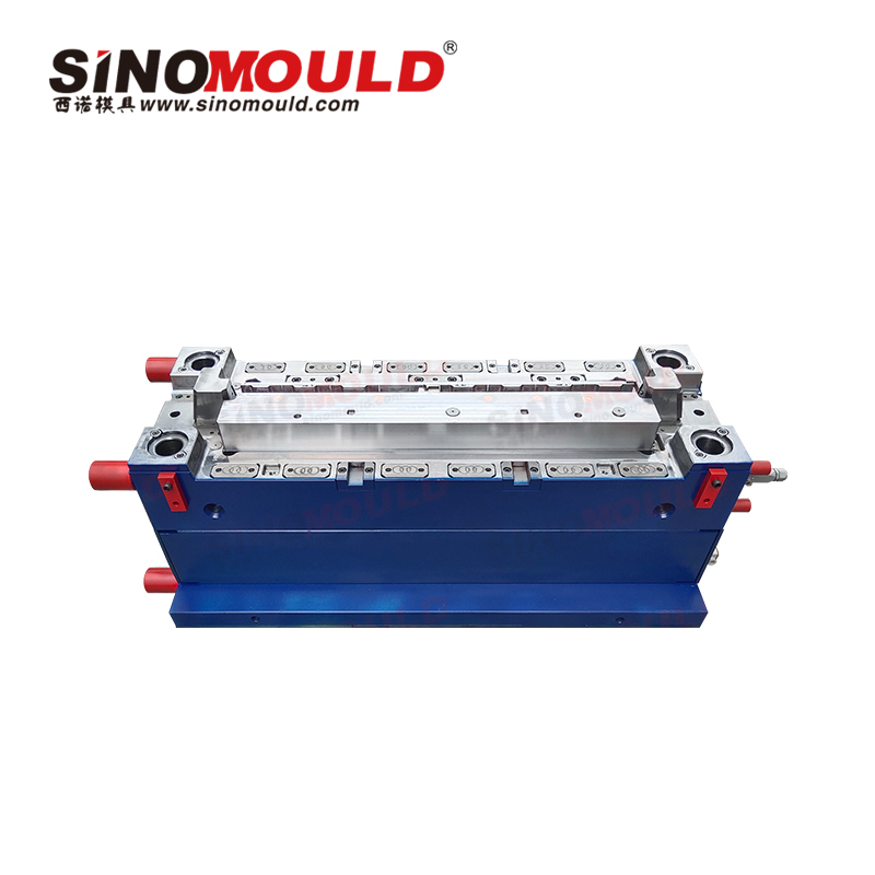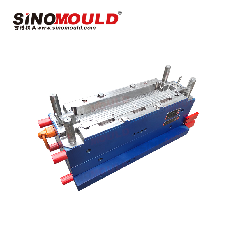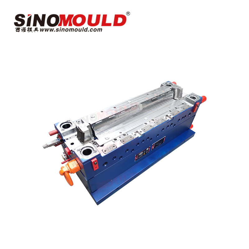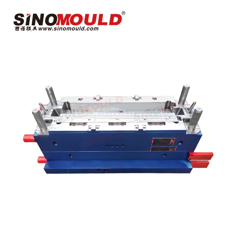
Air Conditioner Flap Mould
The air conditioner flap (vane/blade) is a core component in the air conditioning system that controls airflow, air velocity, and air distribution. Its quality directly affects the air supply efficiency and noise level of the air conditioner. Such products typically present technical challenges including thin blades, high cavity count, and stringent dynamic balance requirements, placing extremely high demands on mould machining precision, cavity consistency, and demoulding reliability.
With over 20 years of experience in the R&D and manufacturing of precision moulds for home appliances, our company specializes in the design and manufacturing of air conditioner flap moulds. Through mould flow analysis optimisation, high-precision 5-axis machining, and a strict quality control system, we provide customers with full-process services from product optimisation to mass production – ensuring that parts meet dynamic balance requirements, operate smoothly, and maintain low noise levels. The following is a comprehensive introduction from three perspectives: mould specifications, quality control, and machining essentials.
Air Conditioner Flap Mould Specifications
| Mould Cavity Steel | S136, P20, 718H | Compatible Injection Molding Machine | 600T two‑platen injection molding machine |
|---|---|---|---|
| Mould Core Steel | S136, P20, 718H | Raw Material MFI | AS/ABS: 6–10 g/10min (220°C, 10kg) |
| Mould Base Standard / Steel | LKM standard / P20, 50C | Ejection System | Uniformly distributed ejector pins + stripper plate, optional air‑assist ejection |
| Sliders, Inserts, Lifters Steel | High‑strength tool steel, nitrided / surface hardened | Injection Process | Precision injection molding, mould temperature control ±2°C, optional gas‑assist molding |
| Number of Cavities | 1 cavity | Injection Cycle Time | 30–60 seconds (depending on part size and material) |
| Hot Runner System | Valve‑gated hot runner / pin‑point gate system | Mould Manufacturing Lead Time | 45–70 days |
Air Conditioner Flap Mould Quality Control Essentials
- Dynamic Balance Accuracy Control
Dynamic balance of the flap product is a core quality indicator, directly affecting operational noise and service life. It is essential to ensure consistent weight and contour dimensions for each blade, with cavity machining accuracy controlled within ±0.02 mm. Hot runner valve gates are used to control the amount of melt entering each cavity, enabling dynamic adjustment of the balance.
- Blade Dimensional and Positional Accuracy
The blades are thin (can be as thin as 1 mm) and numerous (up to 30 blades). The spacing and positional accuracy between blades directly affect product smoothness. Wire EDM or 5‑axis simultaneous machining is required to ensure uniform blade dimensions, with profile contour error ≤0.02 mm.
- Surface Quality Requirements
The finished product surface should be smooth, free from flash, weld lines, sink marks, and bubbles. The mould cavity surface must be precision‑polished or textured to ensure product appearance meets home appliance industry standards.
- Material Selection and Process Stability
Common materials for air conditioner flaps include AS+20% glass fiber, ABS, PP+glass fiber, etc. Strict control of material drying and MFI is required to ensure stable melt flowability. The dynamic balance yield rate must be consistently maintained above 99%.
- Mould Trial Verification and 100% Dynamic Balance Inspection
Mass‑production simulation mould trials are conducted in our in‑house injection workshop. Each batch undergoes 100% dynamic balance inspection, including shaft hole dimensions and blade tip runout, to ensure compliance before delivery.
Air Conditioner Flap Mould Machining Essentials
- High‑Precision Cavity Machining
Flap surfaces are spatial curved surfaces. If a one‑piece cavity is used, machining is extremely difficult. A split‑type modular mould structure is recommended to facilitate machining and maintenance. Blade surfaces are machined with 5‑axis simultaneous milling, achieving surface roughness Ra ≤0.15 μm; wire EDM is used to ensure uniformity of blade spacing.
- Runner System Design
A hot runner + pin‑point gate / valve‑gate system is recommended to ensure equal filling pressure and balanced melt inflow to each cavity, thereby ensuring consistent dimensional quality of each blade. Where conditions permit, gas‑assist injection molding can be used to form stable air cavities inside the blades, reducing product weight.
- Cooling System Optimization
Two‑layer (moving and fixed halves) annular cooling channels or conformal cooling design, with independent zoned mould temperature control, maintaining temperature variation within ±2°C – ensuring consistent cooling rates across all areas and reducing internal stress and warpage.
- Demoulding Mechanism Design
Demoulding is challenging due to the large number of thin blades. Ejector pins should be evenly distributed between blades, combined with a stripper plate structure to ensure balanced ejection force and smooth demoulding, preventing deformation or sticking. Draft angle is generally controlled at approximately 0.5°.
- Venting System Design
Flap products have numerous blades and narrow cavities. An efficient venting system must be designed at the parting line and blade areas to prevent gas traps that cause burning or short shots during high‑speed injection, ensuring complete material filling.
- Machining Equipment Assurance
Critical components are machined using high‑precision equipment such as high‑speed CNC, wire EDM, and precision EDM, with full‑dimensional inspection using CMM to ensure mould fit accuracy and service life.