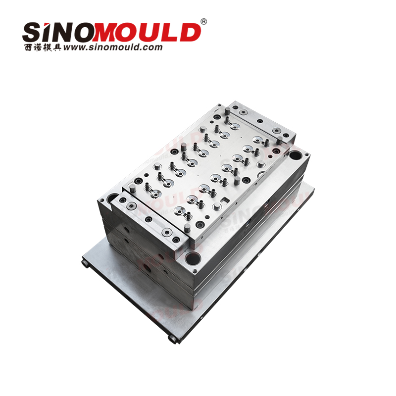
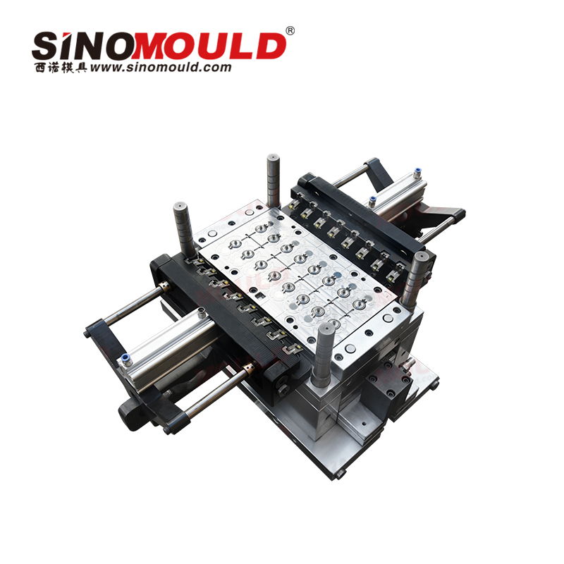
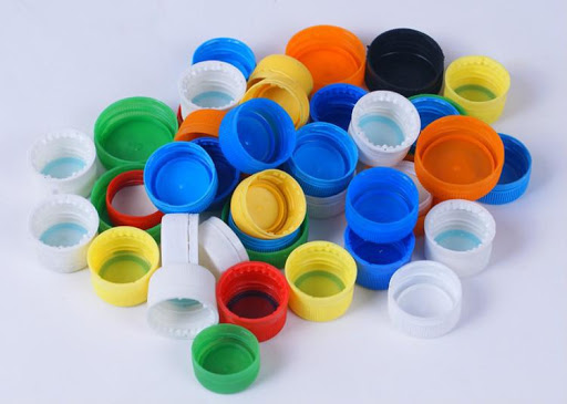
Cap Mould
Precision-engineered cap compression moulds for high-speed production. Superior cooling design, reliable ejection systems, and consistent quality for beverage, pharmaceutical, and industrial closures. Boost output with SINOMOULD’s custom, durable tooling solutions. With over 20 years of experience in R&D and manufacturing of cap moulds, SINOMOULD specializes in custom multi-cavity cap injection moulds for beverage caps, water caps, daily chemical caps, pharmaceutical caps and industrial closures.
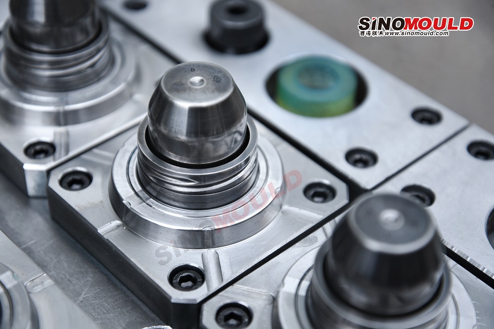
Our company applies Copper Beryllium (Mouldmax) on the core and key cooling areas of cap moulds, achieving excellent cooling effect and stable moulding for high-speed injection. We produce thousands of sets of cap moulds annually. Combined with our parent company DKM high-speed injection moulding machines, we provide turnkey solutions from mould to complete production line for efficient and stable mass production.
Standard Cap Mould Details
Below are examples of common parameters for cap moulds.
| Cap Mould Cavity Steel | P20, 718H, S136, DIN 1.2316; beryllium copper alloy Mouldmax used for critical cooling areas | Cap Mould Core Steel | P20, 718H, S136, DIN 1.2316; Mouldmax beryllium copper alloy used on top and thread areas for enhanced cooling |
|---|---|---|---|
| Mould Base Standard / Steel | Standard mould base, 45#, P20, 4Cr13 pre‑hardened steel | Steel for Sliders, Inserts, Lifters | High‑strength tool steel, nitriding / surface hardening, wear‑resistant and smooth |
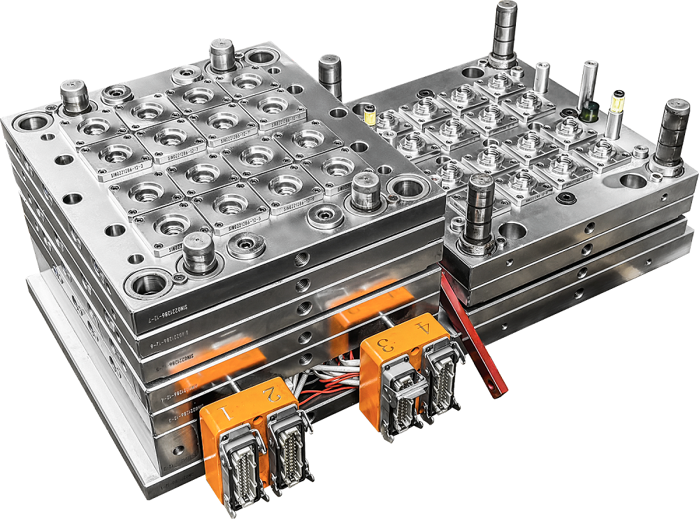
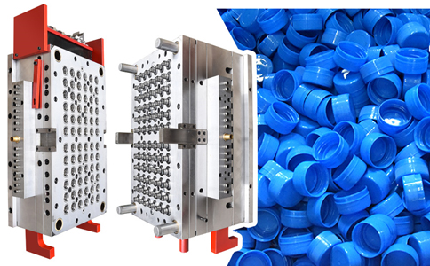
| Number of Cavities | 16, 32, 48, 72, 96, 128 cavities (customized per requirement) | Cap Mould Hot Runner Type | Valve‑gated hot runner / open hot runner |
| Compatible Injection Machine for Cap Mould | DKM high‑speed injection moulding machine series | Raw Material MFI for Cap Mould | PP, PE, typical MFI 5–20 g/10min |
| Cap Mould Ejection Method | Stripper plate + ejector pins + unscrewing structure | Cap Mould Injection Moulding Process | High‑speed injection, precise temperature control, rapid cooling, stable moulding |
| Cap Mould Cycle Time | 4 – 10 seconds | Cap Mould Manufacturing Lead Time | 7–15 days; non‑standard: 15–35 days |
Technical Analysis of Cap Moulds
- If cooling water flows unevenly in different areas of the core and cavity, it will cause differences in molten plastic flow. Hotter areas have better flow and thicker walls; colder areas have weaker flow and thinner walls. Normal temperature difference alone can cause a tolerance of about 0.05mm in wall thickness, affecting sealing and capping fitting.
- The height of the zero-degree interlock in cap moulds is suggested to be 20%–30% of the cap height: around 20% for low cavities and about 30% for high cavities, ensuring uniform clamping and reducing eccentricity and thread misalignment.
- During the machining of core, cavity and thread for cap moulds, high-precision processing equipment must be carefully selected to ensure concentricity and dimensional accuracy, avoiding eccentricity, leakage and poor capping from the source.
Key Quality Points of Cap Moulds
SINOMOULD implements strict quality control for cap moulds. From steel selection, structural design, precision machining to mould trial validation, the whole process ensures high precision, stability and long service life.
Cap Mould Structural Optimization Design
- Optimize cooling channels according to cap structure to ensure even temperature distribution and solve uneven wall thickness.
- Adopt Copper Beryllium (Mouldmax) for key cooling areas, greatly improving cooling efficiency in high-speed injection.
- Optimize runner and gate via mould flow analysis for uniform filling, less sink marks and deformation.
Cap Mould Steel Material Selection
- Core and cavity use high-polish, wear-resistant mould steel, with Copper Beryllium alloy at key positions.
- Mould base adopts high-strength rust-proof steel suitable for long-term mass production.
- Hot runner, slides and unscrewing mechanism use high-temperature and wear-resistant materials.
Cap Mould Machining Precision Control
- High-precision CNC machining with strict tolerance control.
- Multi-stage inspection for parallelism, perpendicularity, concentricity, water sealing and thread accuracy.
- Mirror polishing on cavity ensures smooth and flawless cap surface.
Cap Mould Assembly & Mould Trial
- Precise assembly of unscrewing, slides and ejection system for smooth operation.
- Focus on wall thickness uniformity, dimension, appearance, thread fitting and sealing performance during trial.
- Adjust process and mould structure timely to ensure stable high-speed production.
Cap Mould Validation & Continuous Optimization
- Long-time continuous production test before delivery to simulate real mass production.
- Comprehensively verify reliability of cooling system, hot runner and mechanical movements.
- Continuously optimize mould structure and cooling solution based on field data.
Mould Flow Analysis for Cap Moulds
Using Mouldflow analysis software, we simulate the whole injection process, optimize cavity structure, runner layout and cooling system, ensuring balanced multi-cavity filling and uniform plastic distribution, reducing risks of eccentricity, sink marks, warpage and air traps.
Cap Mould Testing Video
Demonstrating the performance of the centrifuge tube mould under high-speed injection moulding conditions, verifying its stability and efficiency in production.